NB/T 10861-2021 "design specification for the configuration of measuring devices in hydroelectric power plants" provides detailed requirements and guidance for the configuration of measuring devices in hydroelectric power plants.Measuring device is an important part of the operation monitoring of the hydroelectric power plant.The measurement of the hydroelectric power plant is mainly divided into electrical quantity measurement and non-electric quantity measurement.Electrical measurement refers to the measurement of electrical real-time parameters by means of electricity, including current, voltage, frequency, power factor, active/reactive power, active/reactive energy, etc.; non-electricity measurement refers to the use of transmitters to convert non-electricity Measure 4-20mA or 0-5V electrical signals, including temperature, speed, pressure, liquid level, opening, etc.This essay only discusses the measuring device and power consumption management system of the hydroelectric power plant according to the standard, and does not involve the microcomputer protection configuration of the hydroelectric power plant.
1. General Provision
1.0.1 This specification is formulated to standardize the configuration design of measuring devices in hydroelectric power plants, ensure the long-term, safe and stable operation of hydroelectric power plants, and improve the overall comprehensive economic benefits of hydroelectric power plants.
1.0.2 This specification is applicable to the configuration design of measuring devices for newly built, rebuilt and expanded hydroelectric power plants.
1.0.3 The configuration design of measuring devices in hydroelectric power plants should actively adopt new technologies and products that have passed the appraisal.
1.0.4 The configuration and design of measuring devices in hydroelectric power plants should meet the requirements of the power system for the amount of information collected at the power station and the method of information collection.
1.0.5 The configuration design of measuring devices in hydroelectric power plants shall not only conform to this code, but also comply with the current relevant national standards.
2. Terminology
2.0.1 Electrical measuring
Measurement of electrical real-time parameters by means of electricity.
2.0.2 Energy metering
Measurement of electric energy parameters.
2.0.3 General electrical measuring meter
Hydroelectric power plants often use pointer meter, digital meter and so on.
2.0.4 Pointer-type meter
According to the relationship between the pointer and the scale to indicate the measured value of the meter.
2.0.5 Digital-type meter
In the display can use digital directly show the measured value of the meter.
2.0.6 Watt-hour meter
An instrument that measures active and/or reactive electrical energy data.
2.0.7 Intelligent AC sampling device
AC frequency power sampling, directly to the data processing unit for processing to get the voltage, current, active power, reactive power, power factor, frequency, active power, reactive power and other parameters, and through the standard communication interface output multi-functional intelligent meter.
2.0.8 Transducer
Be measured by the conversion of DC current, DC voltage or digital signal device.
2.0.9 Measuring instrument accuracy class
Measuring instruments and/or accessories to meet certain measurement requirements designed to ensure that the permissible error and change extremely within the specified limits of the level.
2.0.10 Automation components
Components and/or devices for condition data monitoring, action execution in hydroelectric plants.
2.0.11 Non-electricity measuring
Measurement of temperature, pressure, speed, displacement, flow, level, vibration, pendulum and other non-electricity real-time parameters.
3. Electrical measurement and power measurement
Electrical measurement objects include hydro generator/generator motor, main transformer, line, bus, plant transformer, DC system and so on.Figure 1 is a schematic diagram of the electrical wiring of the hydroelectric power plant, showing the electrical wiring of the hydroelectric generator set, main transformer, line, and plant power transformer.
Fig. 1 Schematic diagram of electrical wiring of a hydroelectric power plant
3.1 Electrical measurement and electric energy metering of hydroelectric generator/generator motor.

3.1.2 The static variable frequency starting device of the generator motor should measure the following items.
3.1.3 The hydro-generator/generating motor shall measure the active and reactive electric energy. A hydro-generator that may be operated in phase modulation should measure bidirectional active power; a hydro-generator that may be phase-advanced should be measured in bidirectional reactive power; a generator motor should be measured in bidirectional active power and bidirectional reactive power.
3.1.4 For hydro-generators that may be operated in phase modulation, the active power in both directions shall be measured; for hydro-generators that may be operated in phase advance, the power in both directions shall be measured.Generator motors should measure active power and reactive power in both directions.
3.1.5 When measuring the active power angle of the power system, the power angle of the generator should be measured .
3.1.6 The high voltage side of the excitation transformer should measure the three-phase current, active power and reactive power.
The monitoring configuration of hydro-generator and excitation transformer is shown in Fig. 2, and the equipment selection is shown in Fig. 1.
Fig. 2 Electrical measurement configuration of hydro-generator
Table 1 Monitoring selection of hydro-generator and excitation transformer
3.2 Electrical measurement and electric energy metering of boosting and sending system
3.2.1 Main transformer measurement and power metering items shall meet the following requirements :
1 Double-winding transformers should measure the three-phase current, active power, and reactive power on the high-voltage side, and one side of the transformer should measure active energy and reactive energy.
2 Three-winding transformers or auto transformers should measure three-side three-phase current, active power, and reactive power, and should measure active energy and reactive energy on three sides. The auto transformer common winding should measure the three-phase current.
3 When the generating unit is wired as a unit but the generator has a circuit breaker, the low voltage side line voltage and three-phase voltage should be measured..
4 Active power and reactive power should be measured on both sides of the contact transformer, and active energy and reactive energy should be measured.
5 When it is possible to transmit and receive power, the active power in both directions should be measured and the active energy in both directions should be measured; when it is possible to run in phase lag and phase advance, the reactive power in both directions should be measured and the reactive energy in both directions should be measured.
Fig. 3 Electrical measurement configuration of main transformer in hydroelectric power plant
Table 2 Selection of main transformer monitoring
3.2.2 Line measurement items shall meet the following requirements:
1 6.3kV ~ 66kV lines should measure single-phase current, and when conditions permit, two-phase current or three-phase current can be measured.
2 35kV and 66kV lines should measure active power, and 6.3kV ~ 66kV lines can also measure active power and reactive power when conditions permit .
3 110kV and above lines should measure three-phase current, active power and reactive power.
4 6.3kV and above lines should measure active energy and reactive energy.
5 When the line is likely to transmit and receive power, the active power in both directions should be measured and the active energy in both directions should be measured.
6 When the line may run with a phase lag or a phase advance, the reactive power in both directions should be measured and the reactive energy in both directions should be measured.
7 When required by the power system, the power angle of the line should be measured for the line of the step-up station.
Fig. 4 Electrical measurement configuration for hydroelectric power plant lines
Table 3 Line measurement selection
3.2.3 Bus bar measurement items shall meet the following requirements:
1 6.3kV and above generator voltage busbars and 35kV , 66kV busbars should measure the busbar voltage and frequency, and measure the three-phase voltage at the same time.
2 110kV and above buses should measure three line voltages and frequencies.
3 6.3kV and above bus tie circuit breakers, bus section circuit breakers, inner bridge circuit breakers, and outer bridge circuit breakers should measure AC current, and 110kV and above should measure three-phase current.
4 Three-phase current should be measured for each circuit breaker circuit of 3/2 wiring, 4/3 wiring and corner wiring.
5 Bypass circuit breakers, bus tie or section and bypass circuit breakers, and 35kV and above outer bridge circuit breakers should measure active power and reactive power, and measure active energy and reactive energy.When it is possible to transmit and receive power, the active power in both directions should be measured and the active energy in both directions should be measured; in the case of phase lag and phase advance operation, the reactive power in both directions should be measured and the reactive energy in both directions should be measured.
Fig. 5 Electrical measurement configuration of busbar in hydroelectric power plant
Table 4 Bus measurement selection
3.2.4 Three-phase current and reactive power should be measured for 110kV and above shunt reactor groups, and reactive energy should be measured. 6.3kV ~ 66kV shunt reactor circuit should measure AC current.
Table 5 Reactor measurement selection
3.3 Electrical measurement and energy metering of plant power system
3.3.1 AC current, active power and active energy should be measured on the high-voltage side of the factory power transformer. When the high-voltage side does not have the measurement conditions, it can be measured on the low-pressure side.
3.3.2 AC voltage should be measured for the working busbar of factory electricity. When the neutral point is not effectively grounded, a
Line-to-line and three-phase voltages; when the neutral is effectively grounded, three line-to-line voltages shall be measured.
3.3.3 Three-phase current should be measured for power supply lines in the factory area, and active energy can be measured according to the needs of electric energy measurement.
3.3.4 The three-phase current should be measured for 50kVA and above utility power transformers with lighting loads.
3.3.5 The single-phase current should be measured at least for the motor circuit of 55kW and above .
3.3.6 When the low-voltage side of the factory power transformer is a 0.4kV three-phase four-wire system, the three-phase current should be measured.
3.3.7 The section circuit breaker for factory power shall measure single-phase current.
3.3.8 Diesel generators should measure three-phase current, three-phase voltage, active power and measure active energy.
Fig. 6 Electrical measurement configuration of utility power system of hydroelectric power plant
Table 6 Selection of Electrical Measurement Configuration for Plant Power System
3.4 Electrical measurement of DC power system
3.4.1 The DC power supply system shall measure the following items:
1 DC system bus voltage without step-down device.
2 DC system closing bus voltage and control bus voltage with step-down device.
3 The charging device outputs voltage and current.
4 Battery pack voltage and current.
3.4.2 The battery circuit should measure the floating charge current.
3.4.3 When a fixed valve-regulated lead-acid battery is used, it is advisable to measure the voltage of a single battery or an assembled battery by means of inspection.
3.4.4 DC distribution cabinet should measure the bus voltage.
3.4.5 The DC bus insulation test shall comply with the relevant provisions of the current industry standard "Code for Design of DC Power Supply System in Hydroelectric power Plants" NB/T 10606.
3.4.6 When the DC power system is equipped with a microcomputer monitoring device, the measurement of conventional instruments can only measure the DC bus voltage and battery voltage.
3.5 Uninterruptible Power System (UPS) Electrical Measurements
3.5.1 UPS should measure the following items :
1 Output voltage.
2 Output frequency.
3 Output power or current.
3.5.2 UPS main distribution cabinet should measure incoming current, bus voltage and frequency.
3.5.3 The UPS distribution cabinet can measure the bus voltage.
Figure 7 DC system and battery electrical measurement
Table 7 DC system measurement selection
3.6 Commonly measured electrical measuring instruments and electric energy measuring instruments
3. 6.1 The setting of electrical measuring instruments shall meet the following requirements:
1 The settings of the electrical measuring instruments for routine testing should be able to correctly reflect the operating parameters of the electrical installations.
2 When there is a requirement for remote transmission function, an electrical measuring instrument that transmits electrical parameters by means of data communication or analog output shall be configured.
3 Hydraulic generators, generator motors, double-winding main transformer high-voltage side, three-winding main transformer high-voltage side, medium-voltage side and low-voltage side, can replace the section of the line circuit breaker and the bus-tie circuit breaker, the outer bridge circuit breaker, Angle-connected circuit breakers and lines should be equipped with comprehensive measuring instruments for AC sampling electricity; factory power transformers and power distribution circuits of factory power systems can be equipped with comprehensive measuring instruments for AC sampling.
3.6.2 The settings of the analog screen’s regular measuring instruments should meet the following requirements:
1 When the computer monitoring system does not have an analog screen, the control room should cancel the routine measuring instruments. When the computer monitoring system is equipped with an analog screen, the frequently measured instruments on the analog screen should be simplified, and computer-driven digital instruments can be used.
2 The following electrical measuring instruments should be installed on the simulation screen:
1 ) Active power meters and reactive power meters of hydroelectric generators and generator motors.
2 ) Active power meters and reactive power meters for lines with a voltage of 110kV and above ; active power meters for lines with a voltage of 35kV and above and below 110kV.
3 ) Line voltmeter and frequency meter for 35kV and above buses.
4 ) Total active power meter and total reactive power meter of the whole plant.
5 ) Two-way reactive power meters or active power meters installed on hydro-generators that may run in phase advance or phase modulation; two-way active power meters and reactive power meters are installed on generator motors and lines that may transmit and receive electricity. power meter.
6 ) Other measuring instruments.
3.6.3 The local control unit of the unit should be equipped with an AC sampling power comprehensive measuring instrument, an active power transmitter, and a reactive power transmitter and a stator AC voltage transmitter as required.
3.6.4 The excitation screen should be equipped with DC transmitters for measuring excitation current and excitation voltage.
3.6.5 On-site control units such as switch stations and public equipment should be equipped with comprehensive measuring instruments for AC sampling power and/or power transmitters, and other conventional electrical measuring instruments may not be configured.
3.6.6 The configuration of electrical measuring instruments in the switch gear of the factory power system shall meet the following requirements:
1 The switchgear on the high-voltage side of the factory power transformer should be equipped with a conventional single-phase ammeter and a single-phase AC current transmitter, or a comprehensive star measuring instrument for AC sampling power.When the actual load current of the switchgear on the high-voltage side of the plant power transformer is less than 30% of the rated primary current of the current transformer, the conventional ammeter, the comprehensive measuring instrument for AC sampling electricity or the AC current transmitter can be installed in the switchgear on the low-voltage side of the plant power transformer.
2 If the low-voltage side of the power transformer is a 0.4kV three-phase four-wire system, the switchgear on the low-voltage side of the power transformer shall be equipped with conventional three-phase ammeter and single-phase AC current transmitter, or AC proctor-sample power measuring instrument.
3 The busbar voltage transformer cabinet should be equipped with an AC voltage transmitter or an AC sampling electricity comprehensive measuring instrument for measuring the busbar voltage.In the neutral point non-effectively grounded system, the bus voltage transformer cabinet should be equipped with a changeover switch and a voltmeter to measure a line voltage and three-phase voltage.In the neutral point effective grounding system, the bus voltage transformer cabinet can be equipped with a changeover switch and a voltmeter to measure the three line voltages.
4 Ammeters should be installed in each feeder circuit of the bus section circuit breaker cabinet and feeder cabinet of the plant power system, and the bus section circuit breaker cabinet should be equipped with an AC current transmitter.
3.6.7 The diesel generator control cabinet should be equipped with a comprehensive measuring instrument for AC sampling electricity.
3.6.8 The following circuits should be equipped with multi-function electric energy meters:
1 Stator circuits of hydroelectric generators and generator motors.
2 One side of a two-winding main transformer and three sides of a three-winding main transformer.
3 6.3kV and above lines.
4 Bypass circuit breaker, bus tie and bypass circuit breaker circuit.
5 One side of the factory power transformer.
6 The incoming circuit of the external security power supply.
7 Other circuits that need to measure electric energy.
3.6.9 The type selection and performance of conventional electrical measuring instruments and electric energy measuring instruments shall meet the following requirements:
1 The power measurement of the neutral point not effectively grounded should adopt the AC sampling power comprehensive measuring instrument with three-phase four-wire connection, and the power measurement should be the calculation method of three-phase three-wire. The active and reactive power transmitters should be three-phase three-wire, and the electric energy measurement can use a three-phase three-wire multifunctional electric energy meter.
2 The electricity measurement of the neutral point effectively grounding should adopt the three-phase four-wire AC sampling electricity comprehensive measuring instrument and the active and reactive power transmitter, and the electric energy measurement should use the three-phase four-wire multifunctional electric energy meter.
Minimum requirements for the accuracy of conventional electrical measuring instruments shall comply with the provisions in Table 3.6.9-1.
Note: ★When the comprehensive measuring instrument for AC sampling electric quantity is used for AC current and voltage measurement of other electrical systems except electric energy measurement, its minimum accuracy requirement is 0.5.
The minimum accuracy requirements of transmitters, measuring transformers and measuring shunts shall meet the requirements of Table 3.6.9-2.
5 The measurement range of the pointer measuring instrument should be such that the rated value of the power equipment is indicated at about 2/3 of the instrument scale. For the power value or both sides, the pointer instrument with zero scale in the middle of the scale should be selected.
6 The nominal output value of the transmitter should be 4mA ~ 20mA DC or 4mA ~ 12mA ~ 20mA DC, the upper limit of the nominal value should represent 1.2 times to 1.3 times the rated value to be measured, and take a suitable integer for calibration. The full scale value of the pointer instrument connected to the transmitter should be consistent with the calibrated measured value , the connected digital instrument and the computer monitoring system module should be calibrated according to the measured value calibrated here.
7 The minimum accuracy requirement of the multi-function electric energy meter shall comply with the provisions in Table 3.6.9-3.
8 The multi-function electric energy meter should have the function of recording and timing of loss of pressure. When the multi-function electric energy meter adopts auxiliary power supply, after the auxiliary power supply loses power, there should be records of the number of power failures and their dates.
9 The output and communication interface shall meet the following requirements:
1 ) In addition to the analog output, the power transmitter can also have the output mode of the data communication interface at the same time. The physical connection of the communication and the Shixin protocol should meet the requirements of the computer monitoring system.
2 ) The AC sampling power integrated measuring instrument should have the output mode of data communication interface, and the physical connection and communication protocol of communication should meet the requirements of computer monitoring system. When the dispatching automation system requires the remote workstation information to be sent directly, the AC power sampling integrated measuring instrument should add another communication interface, and the physical connection and communication protocol should meet the requirements of the remote workstation.
3 ) The multifunctional electric energy meter should have a data communication interface output mode. When the dispatch automation system requires data collection and direct delivery, two data communication interfaces should be provided, and each should meet the requirements of the communication physical connection and communication protocol of the computer monitoring system and the dispatch data network.
10 Auxiliary power supplies for transmitters, AC sampling electricity comprehensive measuring instruments, multi-functional electric energy meters and digital display instruments should use DC power supply or UPS power supply.
11 The configuration of the energy meter at the gateway of the system should comply with the current industry standard "Technical Management Regulations for Electric Energy Metering Devices" DUT448 and "Technical Regulations for Design of Electric Energy Metering Systems" DL/T5202 and the terminal of the network and energy billing system in the access system design Regulations.
Table 8 Selection parameters of transmitters, digital instruments, multi-function watt-hour meters and other equipment
3.7 Electrical measurement and electric energy metering secondary wiring
3.7.1 The watt-hour meter at the gateway of the system shall be equipped with special current and voltage transformers or special secondary windings for transformers, and shall not be connected to equipment not related to electric energy measurement.
3.7.2 The selection of the accuracy level of the current transformer used for the electric energy meter at the system gateway shall be carried out in accordance with Clause 7 of Article 3.6.9 of this specification.
3.7.3 110kV and above power distribution equipment, 100MW and above hydroelectric generators and generator motors should use current transformers with a rated secondary current of 1A.
3.7.4 The actual load connected to the secondary winding of the current transformer should be guaranteed to be within the range of 25%~100% rated secondary load.
3.7.5 The rated secondary line voltage of the main secondary winding of the voltage transformer should be 100V.
3.7.6 The actual load connected to the secondary winding of the voltage transformer should be guaranteed to be within the range of 25%~100% rated secondary load.
3.7.7 The secondary wiring of the current transformer for the energy meter at the system gateway should adopt the phase-separated wiring method. When the three-phase four-twisted electric energy meter is used for the electric energy meter at the generator outlet and other electric energy meters, the current transformer can be connected in a star connection; when the three-phase three-wire electric energy meter is used, the current transformer can be connected in an incomplete star connection.
3.7.8 When several measuring instruments are connected to the same secondary winding of the current transformer, the sequence of instrument wiring should be electric energy measuring instrument, indicating or displaying instrument, AC sampling electric comprehensive measuring instrument, and electric quantity transmitter. When the secondary wiring of the current transformer adopts a star or incomplete star connection, the star connection point should not be led to the terminal block after the connection terminal of the instrument is formed, but the current of each phase should be led to the terminal block. Form a star on the terminal strip.
3.7.9 For the secondary winding of the current transformer dedicated to the electric energy meter and the secondary circuit of the special voltage transformer, the junction box should be tested before connecting to the terminal of the electric energy meter, so as to facilitate on-site meter calibration and meter replacement with load.
3.7.10 A low-voltage circuit breaker should be installed on the secondary side of the pressure transformer. When the secondary side is led out by a branch circuit, each branch circuit should be installed independently.
3.7.11 The secondary circuit of the current transformer should have one and only one grounding point; when the current transformer is dedicated for electrical measurement or electric energy measurement, it should be grounded at one point through the terminal row at the power distribution device; if it is shared with other equipment When using a current transformer, the grounding method of the transformer should comply with the relevant provisions of the current industry standard "Code for Design of Secondary Wiring in Hydroelectric Plants" NB/T 35076.
3.7.12 The secondary winding of the voltage transformer star connection should adopt the neutral point one-point grounding method, and the neutral point grounding wire should not be connected in series with equipment that may be disconnected; when the voltage transformer is used for electrical measurement or electric energy measurement If the voltage transformer is shared with other equipment, the grounding method of the transformer should comply with the relevant provisions of the current industry standard "Code for Secondary Wiring Design of Hydroelectric Plants" NB/ T 35076.
3.7.13 The cross section of the cable core wire of the secondary current circuit of the current transformer shall be calculated according to the rated secondary load of the current transformer.When the secondary current is 5A, the cross section of the cable core wire should not be less than 4 mm2; when the secondary current is 1A, the cross section of the cable core wire should not be less than 2.5 mm2.
3.7.14 The cross-section of the cable core wire of the secondary circuit of the voltage transformer shall comply with the following regulations:
1 The voltage drop only connected to the pointer meter should not be greater than 1.5% of the rated secondary voltage.
2 The voltage drop of the integrated AC sampling electric quantity measuring instrument, digital display instrument and electric quantity transmitter connected to it should not be greater than 0.5% of the rated secondary voltage.
3 The voltage drop of the electric energy meter connected to the accuracy level of 0.5 and above should not be greater than 0.2% of the rated secondary voltage.
4 The error reflected by the allowable voltage drop should include the composite error of the ratio difference and the angle difference caused by the voltage mutual inductance and the secondary village wire, and should not be just a single ratio difference.
5 The minimum section of the cable core wire should not be less than 2.5 mm².
4. Plant power management system
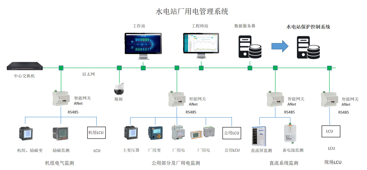
Acrel-3000 power management system for hydroelectric power stations is aimed at hydroelectric generator sets, step-up transformers, outlet circuits, factory transformers and low-voltage parts of factory power, DC screens and batteries of DC systems, and local control units (LCUs) in hydroelectric power stations. Centralized monitoring of the electrical and non-electrical parameters of the power station can also be connected to the protection measurement and control unit in the station to realize power generation and power consumption monitoring, equipment management and operation and maintenance management of the power station.
Figure 7 DC system and battery electrical measurement
Plant overview and one-line diagram display
Generator, Transformer Condition Monitoring
data query
sequence of events recording
control and regulation
Abnormal alarm
Statistics and Tabulation

 Your message must be between 20-3,000 characters!


