Abstract: lighting electricity is a basic power demand of the school. The school has many characteristics, such as large area, large number of rooms, large number of lamps and basic fixed rest time. If the traditional lighting control is adopted, the power waste is often caused by many wiring, unable to make full use of natural light, and the control trouble is inevitable because of forgetting to turn off the lights. In order to achieve the control effect of energy saving optimization, schools can use Smart lighting control system to manage school lighting. Compared with the traditional lighting control mode, the Smart lighting control system has simple wiring, flexible and convenient control, and can save electric energy.
Keyword: School; Lighting; Traditional Lighting; Smart Lighting; Green Energy
0.Background
Acrel Smart Lighting Control system (hereinafter referred to as the system) is based on KNX bus technology, using four-core shielded twisted-pair wire to connect all control modules, such as panel, sensor, driver and bus power supply hand in hand, and integrates various independent control functions into a system, which integrates many advantages, such as comfort, flexibility, safety, energy saving and economy, and convenient maintenance.
Smart and convenient control mode can also meet the various control needs of school lighting. Here is the design and application of Acrel Smart lighting control system in a middle school, a brief analysis of the design specifications of KNX technology, and an overview of the specific structure and control mode of Acrel Smart lighting control system.
1.system composition
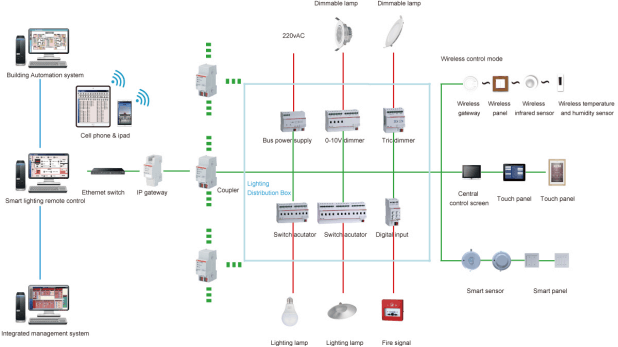
The structure diagram of the system composition is shown in figure 1. The bus power supply, driver, gateway, coupler, input module and so on need to be installed in the distribution box, the sensor is generally installed in the common area, and the panel and touch screen are generally installed in the room duty room. Note that each module wiring can not form a ring. A relatively small project, the system can choose 10 inch central control screen, it does not need to IP the gateway conversion protocol, simple setting and low cost. For relatively large projects, the terminal remote control can be realized by connecting to the computer through the IP gateway.
Network Graph
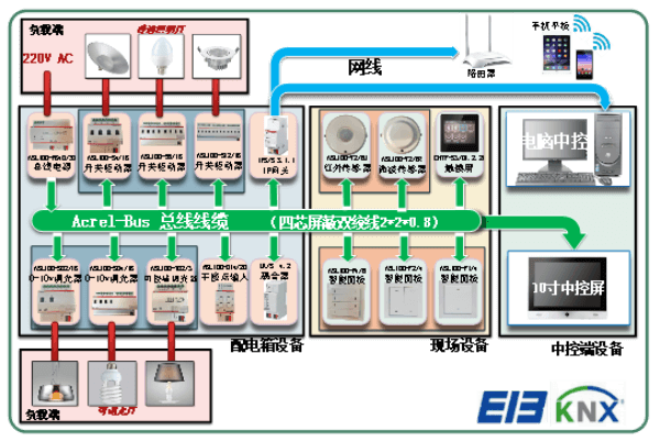
Figure1. Acrel Smart Lighting Control System
2.Project requirements
After communicating with customers, the school requires the following control functions:
1) Fully use of natural illumination for energy saving.
2) Classroom, office can be manually controlled on the spot, but also backstage control.
3) Corridor lamp can be automatically controlled according to the condition of no one and illumination.
4) Realize timing control according to daily class time.
5) Pre-set a variety of scenarios one-click switching control.
6) Control terminal can be one-to-one, one-to-many partition control.
7) Particularly on duty staff can centralized control of school lighting, remote monitoring.
8) Shall be linked to the fire control system.
3.System Function
According to the needs of customers, the project can have a variety of control methods to choose from, such as local control, automatic induction control, timing control, remote centralized control and so on, the control mode is more flexible, while realizing automation, It greatly reduces the management cost of duty personnel and improves the management level and working efficiency.
1) Automatic control:
In common areas such as walkways and elevators, two-in-one sensors can be installed to monitor the illumination of the current environment and whether there is any activity, and to realize automatic control. In the case of sufficient illumination (such as sunny days, noon), someone or no one, the lamp will not light; in the case of insufficient illumination (such as rainy days, nights), someone lights on, people go, the delay lights out.
The illuminance sensor is installed in the window position of the classroom, the teacher's office and other functional areas, and the current illumination situation is monitored in real time. When the illumination is sufficient, the lamp in the window position is automatically closed, and the natural illumination is fully utilized.
2) manual control:
Each classroom, office door is equipped with Smart panel, which can realize manual control of room lighting. Panel can achieve one-to-one, one-to-many control.
3) scene control:
For the school landscape lighting, teaching building hall lighting, important conference room lighting can be based on the control needs of different scenes, set up a variety of scene modes in advance, and by the staff on duty one-click switch.
4) timing control:
According to the time of school early reading and next evening self-study, the system sets the timing switch to complete the automatic control of lighting and ensure the reduction of energy consumption during non-working hours.
5) computer centralized monitoring:
The computer end control page mainly has the home page, the floor control page composition. It can realize remote centralized control, feedback the switch state of field loop in real time, and facilitate remote monitoring of duty personnel.
Monitoring software consists of title bar, task bar and working interface. Title bar: mainly reflects the project name and time. Navigation bar (task bar): you can switch between any page, select. Work interface: according to the floor and room layout, the control is simply divided, can achieve single lamp control, multi-loop control and other control functions.
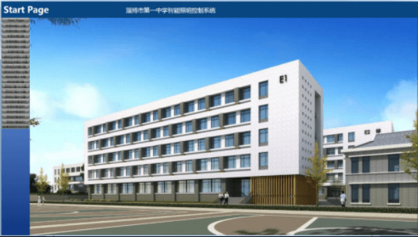
The home page is used as the starting page of the system. The setting content can generally present the project introduction, project effect diagram, project plan, or project structure diagram according to the customer's request. The concrete setting is based on the actual requirements, as shown in figure 2.
The project has a number of floor control pages, with the classroom as the control unit, each classroom has a lighting circuit single switch and main switch, fan air conditioning single switch and main switch, socket power single switch and main switch, floor main switch and field state feedback two state quantities, In addition, there is a timing switch to facilitate users to set their own timing control time.
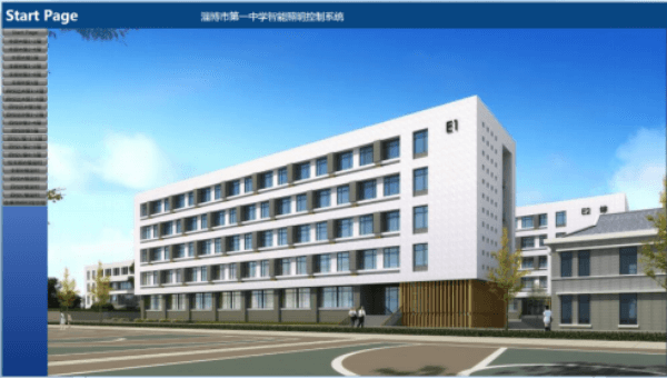
Figure 2. Central Control Platform Home Page
4.Relative Drawing
The school lighting system adopts Acrel-Bus Smart lighting system, because the system adopts KNX distributed bus structure. The wiring is simple and flexible, each module can work independently without influence, and the system reliability is higher. Module working in DC 30V safe voltage, user operation is more secure. When upgrading or changing system functions, you do not need to turn off the whole system, just change the device parameters. System alarm positioning function, real-time monitoring and upload centralized control end, convenient equipment personnel accurate positioning and timely repair. The following is a detailed introduction to the design process of the system through some project drawings.
1)Structure
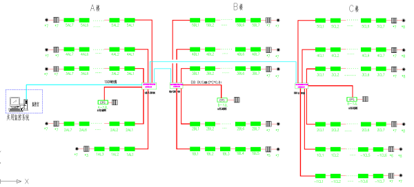
Figure 3. Topology of System Structure
2)Distribution System Diagram
Distribution system diagram mainly defines the control circuit, the required control module and its number, convenient for the later ETS configuration system function. Taking the diagram of Smart lighting and distribution system in a classroom (see figure 4) as an example, it can be seen that the distribution box is allocated a 12-way switch driver, and the module in the box can be connected to the field control panel, sensor and other equipment through the bus cable.
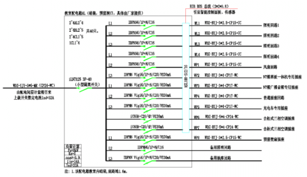
Figure 4. Distribution System Diagram
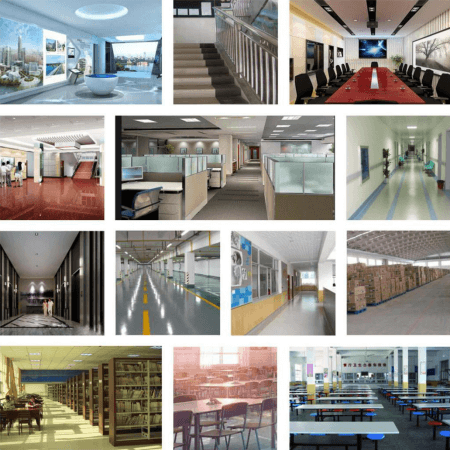
Scene
5.Ending
A detailed introduction is given to the composition, function and design flow of Acrel-Bus Smart lighting system.
In summary, the application of the system in the school has many advantages, such as simple wiring, safe user operation, higher system reliability, convenient maintenance, simple operation and so on. In the implementation of the project, when you deeply realized that the structure of the system is clear, the design and construction is relatively simple, the energy consumption is reduced and the management level is improved in the process of use, and it has great popularization.
Bibliography
1.Solutions For Enterprise Micro-grid System 2020.02

 Your message must be between 20-3,000 characters!
 Please check your E-mail!
  Your message must be between 20-3,000 characters!
 Please check your E-mail!
